Desire Hydraulics is a Die Spotting Press Machine Manufacturer designing and building custom-engineered Hydraulic Die Spotting Presses from 50 Ton to 500 Ton in-house at MIDC Bhosari, Pune — with table/bolster size, stroke, daylight, fixed or moving bolster, tilting arrangement, hydraulic die clamping, fine/micro inching and manual, semi-automatic or PLC/HMI control sized to your die tryout, mould fitting, blue spotting and die matching requirement, and tested before dispatch to tool rooms across Pune, Nashik, Aurangabad, Gujarat, Bangalore, Kerala, Maharashtra, India and the UAE.
Tilting-table die spotting presses built for die tryout, spotting and tool room work — click any photo to view it larger.
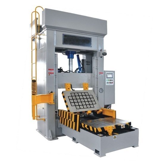
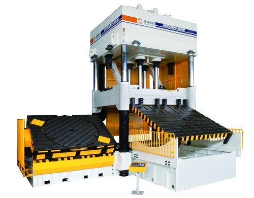
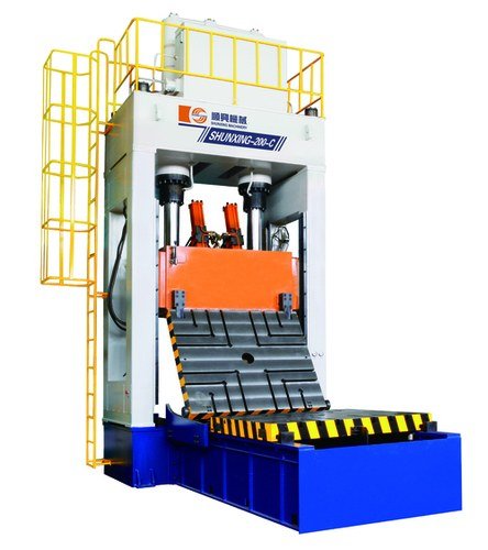
A Die Spotting Press Machine is a specialized Hydraulic press used for die tryout, mould fitting, die matching, blue spotting, tooling inspection, die correction, maintenance and new tool development. It is not simply a Hydraulic press with a large table — its design has to provide controlled movement, accurate stopping, stable guiding, adequate daylight, good visibility of the die surfaces and enough flexibility for the toolmaker to inspect and correct the die.
Desire Hydraulics manufactures Die Spotting Press Machines in-house at MIDC Bhosari, Pune, Maharashtra, in capacities from 50 Ton to 500 Ton, with the table or bolster size, stroke length, daylight, hydraulic system, guiding arrangement, tilting mechanism, moving bolster, die clamping arrangement and control system selected around the customer's die, mould and production requirement rather than a fixed catalogue model.
Every frame, cylinder, bolster and control panel is fabricated, assembled and tested at our own facility before a Die Spotting Press is cleared for dispatch — the same in-house approach behind the hydraulic machines we've delivered to tool rooms, die manufacturers, mould manufacturers and automotive component plants across Pune, Nashik, Aurangabad, Gujarat, Bangalore, Kerala, Maharashtra, India and the UAE.
A Die Spotting Press Machine is a specialized Hydraulic machine used for setting, checking, matching, adjusting and correcting dies and moulds before they are placed into production. Unlike a conventional production Hydraulic press, a Die Spotting Press is designed around the requirements of the toolmaker rather than around tonnage alone.
During die spotting, the operator needs to position the die on the bolster, close it slowly, check contact between the upper and lower die surfaces, identify high spots, apply spotting compound or blueing material, inspect the contact pattern, make corrections and repeat the closing and inspection process — rotating or tilting the tooling where required. This makes the Die Spotting Press an important machine in tool rooms, die manufacturing companies, mould manufacturing facilities and automotive component plants.
A hydraulic die spotting press uses hydraulic power to control the movement of the machine slide or upper table, with the circuit configured for a fast approach followed by a slow, controlled spotting speed and controlled return.
The die is positioned on the lower bolster and secured using the appropriate hydraulic or mechanical clamping arrangement, with the upper portion of the die positioned to match.
The hydraulic circuit brings the slide toward the die at a faster speed while the tooling is still clear of contact, keeping the overall cycle time short.
As the slide nears the spotting position, the operator switches to slow approach, fine inching or micro-inching so the die closes under controlled, low-speed movement rather than full speed.
The die is brought into controlled contact under spotting pressure. Spotting compound or blueing material applied to a tooling surface transfers to the mating surface at the points of contact.
The die is opened and the toolmaker inspects the transferred pattern to identify high-contact areas, low-contact areas, uneven contact, misalignment and areas requiring polishing or machining.
Tool corrections are carried out and the closing, inspection and correction cycle is repeated until the required die contact and alignment are achieved, ready for die tryout or production.
A properly engineered Hydraulic Die Spotting Press consists of several integrated systems working together to give the toolmaker controlled movement, visibility and repeatable accuracy. The exact configuration depends on the die, mould and application.
Guiding is critical because die spotting involves checking the relationship between two tooling halves — a suitable guide column, bush or linear guiding arrangement helps maintain controlled movement and parallelism throughout the cycle.
Standard on every unit, and adjusted to your die, mould and tooling requirement before fabrication begins.
Press capacity engineered to your die weight, projected area and required spotting force rather than tonnage alone.
Table dimensions from approximately 1000 x 800 mm up to 3600 x 2400 mm and larger, sized to your die or mould.
Controlled, low-speed closing near the spotting position for precise, repeatable die contact.
Upper table, lower table or bolster tilting, including high-angle configurations up to approximately 180° on suitable machines.
Straightforward push-button control as standard, with PLC sequencing and HMI monitoring available on request.
Every cylinder, bolster and control panel assembly is run and checked under load before it leaves our floor.
Every Die Spotting Press is engineered to the tooling rather than sold on tonnage alone — these ranges reflect what we commonly build; exact figures are confirmed against your die or mould drawing.
| Press capacity | 50, 75, 100, 125, 150, 200, 250, 300, 350, 400, 450 and 500 Ton |
|---|---|
| Table / bolster | Approx. 1000 x 800 mm and upward, up to 3600 x 2400 mm and larger |
| Stroke | Approx. 500 mm to 2700 mm depending on application |
| Daylight | Application-specific, engineered around closed and maximum die height |
| Bolster | Fixed or moving, according to die weight and handling requirement |
| Tilting | Optional; upper table, lower table or bolster, up to approximately 110–180° where suitable |
| Die clamping | Optional hydraulic or mechanical clamping arrangement |
| Control | Manual, push-button, semi-automatic, PLC or PLC + HMI, with fine/micro inching available |
Looking for an exact table size, stroke or tilting angle? Share your die or mould dimensions, weight and centre of gravity and we'll size the press against it.
Die Spotting Presses can be configured by bolster movement, tilting arrangement, control system and application. The right configuration depends on the die, mould, weight, centre of gravity and required handling method.
A conventional fixed lower table suited to tool rooms with moderate die sizes and standard loading arrangements.
The lower bolster shifts outward to simplify die loading, unloading and crane access, especially for heavier tooling.
Upper table, lower table or bolster tilting arrangement for better access to difficult areas of a large die or mould.
Direct push-button operator control over up/down movement, approach, pressing, return and inching.
PLC-managed sequence, pressure and stroke control with an HMI touchscreen for monitoring position, cycle status and alarms.
Integrated hydraulic clamping reduces manual clamping work and makes tooling setup more repeatable.
Proportional valves and position feedback deliver precision, low-speed movement during the final spotting operation.
Large bolster, high daylight, long stroke and moving-bolster configuration for automotive body and sheet metal dies.
Engineered from the die drawing, weight and handling method rather than selected from a fixed catalogue model.
Die Spotting Presses are used across tool rooms, die manufacturing companies, mould manufacturing facilities, automotive component plants and engineering industries.
Body dies, sheet metal dies, automotive component dies, progressive dies, tool tryout and die correction.
Press tools, forming dies, blanking dies, drawing dies and progressive tooling.
New die development, die matching, blue spotting, tryout, correction and final inspection.
Injection moulds, compression moulds, rubber moulds, SMC moulds and FRP moulds.
Custom tooling, special-purpose dies, maintenance, tool modification and industrial mould development.
Verifying die alignment, closing behaviour, contact areas, clearance and mechanical interference before production.
Checking die contact using spotting compound to identify high spots, low spots and misalignment.
Mould matching, parting-line inspection, insert checking, core/cavity alignment and repair.
Die correction, repair and periodic inspection to keep tooling production-ready.
A correctly designed machine can provide several advantages to a tool room, when the design is matched to the application.
Controlled closing makes it easier to identify contact problems and correct them accurately.
The operator can repeatedly inspect and correct the tooling without unnecessary correction cycles.
Tilting and moving-table systems make difficult tooling areas easier to reach and inspect.
Moving bolsters and hydraulic clamping reduce unnecessary manual handling of heavy dies.
Fine inching allows the operator to approach the spotting position carefully and consistently.
A dedicated spotting machine reduces the time required for die tryout, correction and final inspection.
Selecting the machine by tonnage alone is not recommended — the following should be considered before finalizing a press.
Desire Hydraulics is based in Pune, Maharashtra, an important automotive and engineering manufacturing region in India. Our Die Spotting Press solutions are built for tool rooms and die manufacturers in Pune and the surrounding MIDC Bhosari belt, as well as customers across Maharashtra and other parts of India, and for international customers including the UAE.
Machine selection is based on the customer's actual die, mould and tooling requirement rather than a one-size-fits-all approach, whichever of these regions you're supplying from.
Table size, stroke, daylight and tilting sized to your actual die or mould, not a fixed model.
Frame fabrication, machining, assembly and testing all done at MIDC Bhosari.
Hydraulic cylinders, bolster movement and control systems are run under load before the machine ships.
Installation guidance and after-sales service across India and the UAE.
Common questions we hear from tool rooms and die manufacturers evaluating a Die Spotting Press.